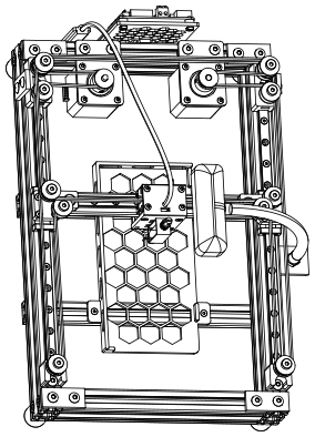
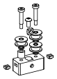
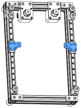
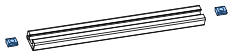
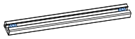
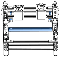
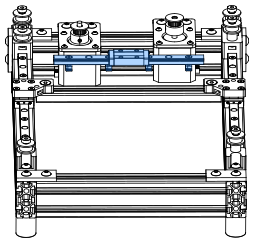
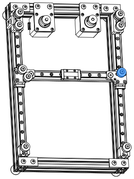
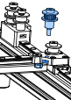
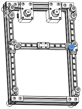
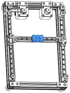
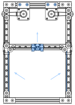
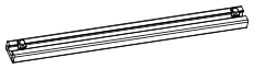
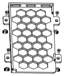
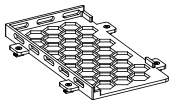
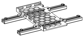
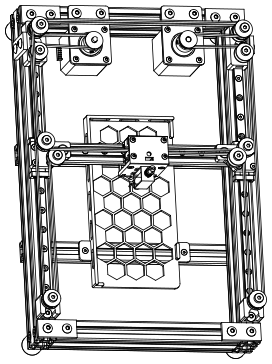
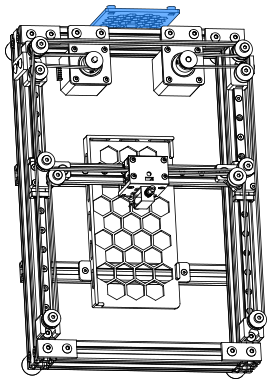
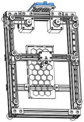
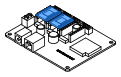
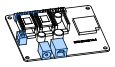
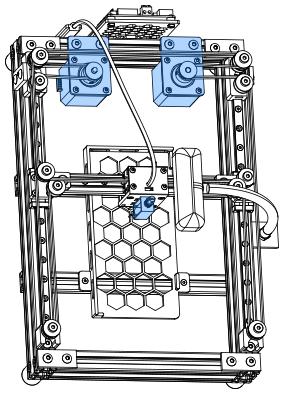
PhysiClaw is a physically interactive agent. It operates a phone by tapping on the screen, so it needs hardware to carry out those taps. This manual covers the assembly of that hardware. The hardware has three parts. A CoreXY stage moves across the X/Y plane. A touch end presses the screen along the Z axis. A camera watches the screen.
Before you begin
Read this manual all the way through. Compare the parts you bought with the bill of materials. Make sure that nothing is missing. Assembly of a PhysiClaw takes about 3 hours, so set aside enough time.
Report an issue
If you find an error in this manual, or have a suggestion, please open an issue on GitHub (github.com/physiclaw/PhysiClaw/issues). Include the page numbers and a short description. Annotated screenshots are also welcome. We update the manual periodically based on the feedback we get.
Domed head, hex drive. Use it where you need a low head but not a flush head.
ISO 7380-1
Flat head cap screw (FHCS)
90° countersunk head, hex drive. The head sits flush with the surface. Use it where nothing can protrude above the part.
ISO 10642 / DIN 7991
Shim
5×8×0.5 shim. Stack shims under each idler to adjust axial play.
5×8×0.5
Hex nut
Pairs with a screw to clamp parts firmly together.
ISO 4032 / DIN 934
Square nut
A square nut sits in a pocket of the printed part, so that a screw can thread into it.
DIN 557
44
HARDWARE — REFERENCEPhysiClaw.ai
Standard T-nut (slide-in)
Slides into the slot from the open end of the extrusion. When you tighten the screw, the nut pulls up and catches on the inner edges of the slot.
Hammer T-nut (drop-in)
Drops flat into the slot anywhere along its length. A quarter turn then locks it.
GT2 drive pulley
20-tooth pulley. One sits on each motor shaft, locked to the D-flat with a set screw. It drives the GT2 belt.
GT2 · 20T · 5 mm bore · 6 mm belt
GT2 idler (toothed)
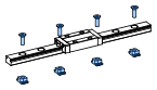
Toothed wheel that meshes with the toothed side of the belt.
GT2 · 20T · 5 mm bore · 6 mm belt
GT2 idler (smooth)
Smooth wheel that rides on the flat back of the belt.
5 mm bore · 6 mm belt
Flat bracket
2-hole plate with M5 holes 20 mm apart.
55
HARDWARE — TOOLSPhysiClaw.ai
Hex key sizes
Use 2 mm for the M3 BHCS/FHCS. Use 3 mm for the M5 BHCS/FHCS. Use 5 mm for the M6 SHCS. You use the 2 mm and 3 mm most, so get a good key of each.
66
3D PRINTED PARTSPhysiClaw.ai
Part printing settings and guidelines
PhysiClaw's custom parts are printed by a nylon powder-bed process, either Selective Laser Sintering (SLS) or Multi Jet Fusion (MJF), not the more common FDM. The powder-bed process fuses nylon powder layer by layer. The parts come out dense, with no supports and the same strength in every direction. These parts have side holes and overhangs. With FDM the side holes deform and the overhangs sag. When you order parts, match the specifications below.
3D Printing Process
Selective Laser Sintering (SLS) or Multi Jet Fusion (MJF)
Part Density
Solid
Material
Black PA12 nylon (or equivalent)
Dimensional Tolerance
±0.3% (min ±0.3 mm)
Layer Thickness
100 µm (0.1 mm)
Orientation
Service default
Minimum Wall Thickness
1.0 mm
Surface Finish
Raw / as-printed
File naming
A file name that ends in _x# gives the quantity of that part in the machine. For example, the machine needs two of idler_mount_front_x2.step.
77
PhysiClaw.ai
SECTION 01
Frame
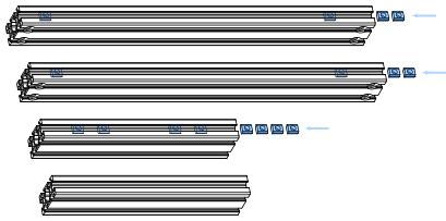
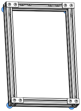
Four aluminum 2040 extrusions form the base frame. Every other part is installed on it. Make sure that all four corners are square. They are the foundation for accurate motion later.
88
FRAMEframe_10PhysiClaw.ai
Load the T-nuts first
Before you square the frame, slide every T-nut into its slot.
Bill of materials
Component
Spec
Qty
Extrusion 2040
345 mm · CB
2
Extrusion 2040
190 mm
2
T-nut
Slide-In M5
8
99
FRAMEframe_20PhysiClaw.ai
Direction convention
Top, bottom, left, and right throughout this manual refer to this view.
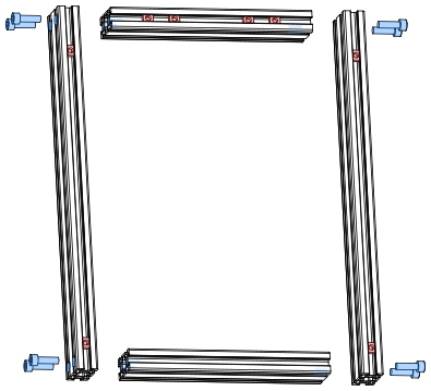
Short extrusion on top
Put the short extrusion with the 4 slide-in T-nuts on top.
Counterbores face out
Turn the counterbored ends of the long extrusions outward. Align each counterbore with the end hole of the short extrusion.
Square before final tightening
1. Drop each M6×20 SHCS through the counterbore into the end hole of the short extrusion. 2. Tighten all 8 until snug. 3. Square the frame on a flat surface. 4. Tighten fully.
Bill of materials
Component
Spec
Qty
SHCS
M6×20
8
1010
FRAMEframe_30 · frame_31PhysiClaw.ai
Reinforce the frame
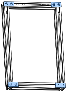
One flat bracket reinforces each corner. 1. Put 2 M5×10 BHCS through the bracket. 2. Thread a drop-in T-nut loosely onto each. 3. Put the bracket with its nuts into the frame corner. 4. Tighten both screws.
Bill of materials
Component
Spec
Qty
Flat bracket
40 × 18 × 4 mm
4
BHCS
M5×10
8
T-nut
Drop-In M5
8
1111
FRAMEframe_40 · frame_41PhysiClaw.ai
Feet point down
The bumpers are the feet of the machine. Install them under the four corners of the frame.
Bumper screws
If the bumpers came with their own screws, use those screws. They are the right size.
Bill of materials
Component
Spec
Qty
Bumper
Ø20 × 22 mm
4
BHCS
M5×16
4
T-nut
Drop-In M5
4
1212
PhysiClaw.ai
SECTION 02
Idler
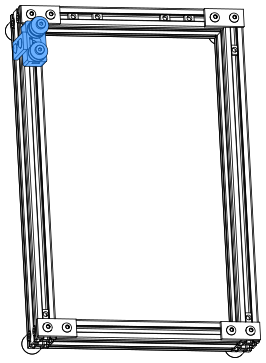
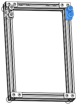
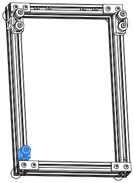
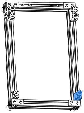
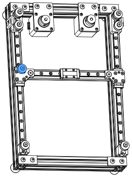
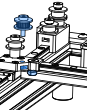
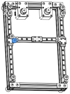
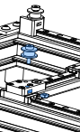
Install one idler assembly at each of the four corners of the frame. All four use smooth idlers. The idlers roll on the flat back of the GT2 belt and turn it around each corner. Every idler mount sits 2 mm clear of the horizontal flat bracket at its corner, so the four corners are symmetric.
1313
IDLERidler_10PhysiClaw.ai
Center screw and nut first
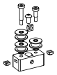
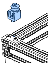
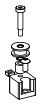
Put the M5 square nut and the M5×10 BHCS into the middle counterbore first. The idler stacks block access to it later.
Check the idlers
After you install the idlers, make sure that each idler turns freely.
Flat face toward the screw
Put each square nut in with its flat face toward the screw.
If a side nut does not go in
The print can leave powder in the pocket. If a side square nut does not go in, clear the pocket with a small screwdriver or a pin.
Bill of materials
Component
Spec
Qty
Idler mount
SLS/MJF 3D Print
1
Idler
GT2 20T, smooth
3
BHCS
M5×10
1
Shoulder screw
Ø5×10×M4
1
Shoulder screw
Ø5×20×M4
1
Square nut
M4
2
Square nut
M5
1
Shim
5×8×0.5
3
1414
IDLERidler_12PhysiClaw.ai
Two attachments to the frame
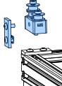
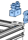
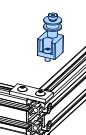
The middle M5 screw threads into a slide-in T-nut in the extrusion slot. The flat bracket bridges the idler mount and the frame. On the bracket, the longer M5×12 BHCS threads into the captive square nut of the idler mount. The M5×10 BHCS threads into the drop-in T-nut in the extrusion slot.
2 mm gap to the corner flat bracket
Put the idler mount 2 mm clear of the horizontal flat bracket at the frame corner.
Bill of materials
Component
Spec
Qty
Flat bracket
40 × 18 × 4 mm
1
BHCS
M5×10
1
BHCS
M5×12
1
T-nut
Drop-In M5
1
1515
IDLERidler_20PhysiClaw.ai
Each idler stack is 18 mm
The idler is 8.5 mm, the spacer 9 mm, a shim 0.5 mm. Use shims and spacers to bring every idler stack to 18 mm.
Spacer must total 9 mm
The spacer is 9 mm tall. If you cannot buy a 9 mm spacer, stack shorter spacers to a total of 9 mm.
Bill of materials
Component
Spec
Qty
Idler mount
SLS/MJF 3D Print
1
Idler
GT2 20T, smooth
3
BHCS
M5×10
1
Shoulder screw
Ø5×20×M4
2
Square nut
M4
2
Square nut
M5
1
Spacer
5×10×9
1
Shim
5×8×0.5
3
1616
IDLERidler_22PhysiClaw.ai
Long screw into the idler mount
Split the screws as at the left idler mount. M5×12 goes into the idler mount, M5×10 into the extrusion slot.
Match the left idler mount's gap
Set the same 2 mm gap as at the left idler mount.
Bill of materials
Component
Spec
Qty
Flat bracket
40 × 18 × 4 mm
1
BHCS
M5×10
1
BHCS
M5×12
1
T-nut
Drop-In M5
1
1717
IDLERidler_30PhysiClaw.ai
Motor A idler on the lower plane
This idler carries the Motor A belt. It has no spacer, so it rides on the lower belt plane.
Bill of materials
Component
Spec
Qty
Idler mount
SLS/MJF 3D Print
1
Idler
GT2 20T, smooth
1
BHCS
M5×10
1
Shoulder screw
Ø5×10×M4
1
Square nut
M4
1
Shim
5×8×0.5
1
1818
IDLERidler_31PhysiClaw.ai
2 mm gap to the corner flat bracket
Put this idler mount 2 mm clear of the horizontal flat bracket at the frame corner too.
1919
IDLERidler_40PhysiClaw.ai
Motor B idler on the upper plane
This idler carries the Motor B belt. The 9 mm spacer lifts it onto the upper belt plane.
Bill of materials
Component
Spec
Qty
Idler mount
SLS/MJF 3D Print
1
Idler
GT2 20T, smooth
1
BHCS
M5×10
1
Shoulder screw
Ø5×20×M4
1
Square nut
M4
1
Spacer
5×10×9
1
Shim
5×8×0.5
1
2020
IDLERidler_41PhysiClaw.ai
Match the left idler mount's gap
Set the same 2 mm gap as at the left idler mount.
2121
PhysiClaw.ai
SECTION 03
Motor
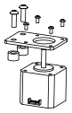
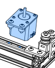
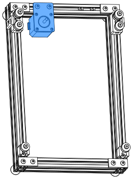
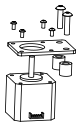
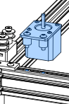
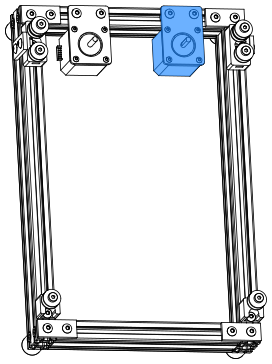
Two NEMA 17 stepper motors sit on the top extrusion of the frame, one at each side. The motors drive the CoreXY belts, which move the X carriage.
2222
MOTORmotor_10PhysiClaw.ai
Note the connector direction
Make sure that the motor connector faces as shown. That direction sets the wiring clearance later.
Spacer height for Motor A
The spacer of Motor A must be 8 mm tall.
Tighten in a cross pattern
1. Thread all 4 motor screws in by hand. 2. Tighten opposite corners in pairs. This pulls the motor flat against the bracket.
Bill of materials
Component
Spec
Qty
Motor bracket
60×42×3
1
Motor
NEMA 17 stepper
1
BHCS
M3×6
4
BHCS
M5×16
2
Spacer
6×12×8
2
2323
MOTORmotor_11PhysiClaw.ai
Motor A
The left motor is Motor A.
Do not fully tighten the screws
Tighten until snug. After you tension the belt, tighten fully.
2424
MOTORmotor_20PhysiClaw.ai
A taller spacer here
The spacer of Motor B must be 12 mm tall.
Right motor mirrors the left
Install it like the left motor, as a mirror image. The motor connector faces right.
Bill of materials
Component
Spec
Qty
Motor bracket
60×42×3
1
Motor
NEMA 17 stepper
1
BHCS
M3×6
4
BHCS
M5×20
2
Spacer
6×12×12
2
2525
MOTORmotor_21PhysiClaw.ai
Motor B
The right motor is Motor B, the mirror image of the left.
Do not fully tighten the screws
Tighten until snug. After you tension the belt, tighten fully.
2626
MOTORmotor_30PhysiClaw.ai
Two heights
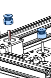
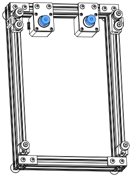
The Motor A belt and the Motor B belt sit at different heights. The pulley of Motor A (left) sits on the lower belt plane. The pulley of Motor B (right) sits on the upper belt plane. Slide each pulley along its motor shaft to its plane.
Set screws
1. Tighten one set screw onto the D-flat of the shaft. 2. Tighten the other.
Threadlocker
Make sure that the pulleys and idlers are aligned. Then apply threadlocker to every set screw. A loose pulley makes the motion inaccurate. It is the most common issue users report. You can also apply the threadlocker after you install the belts.
Bill of materials
Component
Spec
Qty
Pulley
GT2 20T, 6 mm
2
2727
PhysiClaw.ai
SECTION 04
Linear motion
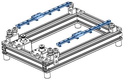
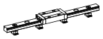
PhysiClaw's X/Y motion is a CoreXY stage on three MGN9H rails. The Y axis uses two rails, one on the left and one on the right. One rail spans between them as the X axis. Each of the two XY joints, where the X axis meets a Y rail, carries two idlers. Keep every carriage on its rail. A carriage that slides off spills its balls and is ruined.
2828
LINEAR MOTIONlinear_10PhysiClaw.ai
Install the carriage
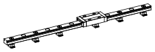
Some carriages ship on a plastic dummy rail. Do not take the carriage off it. The balls can fall out. 1. Align the dummy rail with the end of the rail. 2. Slide the carriage from the dummy rail onto the rail.
Build two Y rails
The Y axis uses two identical rails.
Clean and grease the rails
MGN9H rails ship coated in anti-rust oil. Before you install the rail, wipe the oil off. Put fresh grease on the carriage so that it runs smoothly and lasts longer. Keep the rail away from water at all times.
Load the T-nuts first
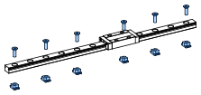
1. Thread an M3×8 BHCS into every hole. 2. Thread a drop-in T-nut onto each screw tip so that it hangs. 3. Lower the rail onto the extrusion so that the T-nuts drop into the slot. 4. Tighten the screws until snug.
Keep the carriage on the rail
Keep the carriage on the rail at all times. If it slides off, the balls fall out and the carriage is ruined.
Bill of materials
Component
Spec
Qty
Linear rail
MGN9H, 240 mm
2
BHCS
M3×8
24
T-nut
Drop-In M3
24
2929
LINEAR MOTIONlinear_11PhysiClaw.ai
Rail ends against the idler mounts
Adjust the idler mounts at the end opposite the motors. Make sure that both Y rail ends sit tight against them.
Do not fully tighten the Y rails
Tighten the screws of both Y rails until snug. Install the X beam first. When it slides smoothly, tighten them fully.
3030
LINEAR MOTIONlinear_20PhysiClaw.ai
Straight side toward the motor
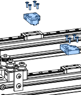
The left and right joints are mirror images. Install each joint with its straight side toward the motor.
Tighten in a cross pattern
1. Thread all 4 screws in. 2. Tighten opposite corners in pairs. This pulls the joint flat against the carriage.
Bill of materials
Component
Spec
Qty
XY joint (left)
SLS/MJF 3D Print
1
XY joint (right)
SLS/MJF 3D Print
1
FHCS
M3×10
8
3131
LINEAR MOTIONlinear_30PhysiClaw.ai
Load the X beam T-nuts first
Slide the 2 M5 T-nuts in, one from each end.
Bill of materials
Component
Spec
Qty
Extrusion 1020
185 mm
1
T-nut
Slide-In M5
2
3232
LINEAR MOTIONlinear_31PhysiClaw.ai
Check the X beam
Slide the X beam along the Y rails by hand. If it binds, realign the Y rails.
Be patient
1. Tighten a few of the Y rail screws until snug. 2. Slide the X beam and feel the resistance. 3. Move the Y rails slightly. 4. Slide the X beam again. 5. When the beam slides freely, tighten the Y rails from the center screw outward. This can take a few minutes.
Bill of materials
Component
Spec
Qty
FHCS
M5×12
2
3333
LINEAR MOTIONlinear_32PhysiClaw.ai
X rail
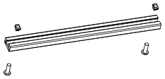
Install this rail like the Y rails. 1. Thread the screws in so that the T-nuts hang. 2. Lower the rail onto the extrusion so that the T-nuts drop into the slot. 3. Tighten the screws.
Bill of materials
Component
Spec
Qty
Linear rail
MGN9H, 150 mm
1
BHCS
M3×8
7
T-nut
Drop-In M3
7
3434
LINEAR MOTIONlinear_33PhysiClaw.ai
Check both axes
Make sure that the carriage slides smoothly along the X rail. Make sure that the whole beam still slides freely along the Y rails. If either binds, realign that rail. Then tighten it again.
3535
LINEAR MOTIONlinear_40PhysiClaw.ai
Motor B idler on the upper plane
This idler carries the Motor B belt on the left joint. The 9 mm spacer lifts it onto the upper belt plane.
Bill of materials
Component
Spec
Qty
Idler
GT2 20T, smooth
1
Shoulder screw
Ø5×20×M4
1
Spacer
5×10×9
1
Shim
5×8×0.5
1
3636
LINEAR MOTIONlinear_41PhysiClaw.ai
Use the correct hole
Install the idler in the top hole of the left joint.
Bill of materials
Component
Spec
Qty
Square nut
M4
1
3737
LINEAR MOTIONlinear_42PhysiClaw.ai
Motor A idler on the lower plane
Use the toothed idler here, not the smooth one.
This idler carries the Motor A belt. It has no spacer, so it rides on the lower belt plane.
Bill of materials
Component
Spec
Qty
Idler
GT2 20T, toothed
1
Shoulder screw
Ø5×10×M4
1
Shim
5×8×0.5
1
3838
LINEAR MOTIONlinear_43PhysiClaw.ai
Bill of materials
Component
Spec
Qty
Square nut
M4
1
3939
LINEAR MOTIONlinear_44PhysiClaw.ai
Motor A idler on the lower plane
This idler carries the Motor A belt on the right joint, in the top hole. It has no spacer, so it rides on the lower belt plane.
Bill of materials
Component
Spec
Qty
Idler
GT2 20T, smooth
1
Shoulder screw
Ø5×10×M4
1
Shim
5×8×0.5
1
4040
LINEAR MOTIONlinear_45PhysiClaw.ai
Bill of materials
Component
Spec
Qty
Square nut
M4
1
4141
LINEAR MOTIONlinear_46PhysiClaw.ai
Motor B idler on the upper plane
Use the toothed idler here, not the smooth one.
This idler carries the Motor B belt on the right joint. The 9 mm spacer lifts it onto the upper belt plane.
Bill of materials
Component
Spec
Qty
Idler
GT2 20T, toothed
1
Shoulder screw
Ø5×20×M4
1
Spacer
5×10×9
1
Shim
5×8×0.5
1
4242
LINEAR MOTIONlinear_47PhysiClaw.ai
Check all four idlers
Make sure that each idler sits in its correct hole.
Bill of materials
Component
Spec
Qty
Square nut
M4
1
4343
PhysiClaw.ai
SECTION 05
Belt path
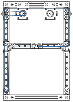
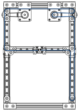
PhysiClaw's CoreXY stage runs on two GT2 belts, the Motor A belt and the Motor B belt. They run on the upper and lower belt planes, so they never cross. The two belts must have equal tension, or the motion is not accurate.
4444
BELT PATHbelt_10 · belt_11PhysiClaw.ai
Install the Motor A belt
The Motor A belt is a single open length. Both ends clamp to the X carriage. Keep the belt flat in one plane along the whole path. The teeth run on the pulley and the toothed idlers. The smooth back runs on the smooth idlers.
The clamp locks itself
1. Feed each belt end into the bottom slot of the clamp. 2. Loop it around the post. 3. Fold it back against itself so that the teeth mesh. The meshed teeth hold the belt with no extra fasteners.
Slide the motor to tension the belt
Keep the 2 M5 screws of Motor A snug, not tight. 1. Clamp both belt ends. 2. Slide the motor to tension the belt.
Bill of materials
Component
Spec
Qty
Timing belt
GT2-6 mm, open-ended
1
4545
BELT PATHbelt_20PhysiClaw.ai
Clamp the belt, then install the clamp
Before you install the clamp on the X carriage, make sure that the Motor A belt sits in the bottom slot of the clamp.
Match the Motor B belt length
Before you put the Motor A belt into its clamp, cut the Motor B belt to the same length.
Bill of materials
Component
Spec
Qty
Belt clamp
SLS/MJF 3D Print
1
BHCS
M3×8
4
4646
BELT PATHbelt_30 · belt_11PhysiClaw.ai
Install the Motor B belt
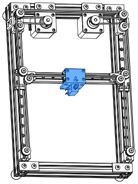
Route the Motor B belt on the upper belt plane. It must not cross the Motor A belt. Clamp both ends to the X carriage, the same way as the Motor A belt.
Check the belts
After you install both belts, slide the X carriage by hand through its full travel in every direction. The carriage must slide smoothly, with even resistance throughout. That resistance comes only from the motors. Make sure that nothing sticks, interferes, twists, or makes an odd noise. Make sure that the two belts stay on their separate planes.
Threadlocker
The pulleys are now aligned. If their set screws have no threadlocker yet, apply it now.
4747
BELT PATHbelt_30PhysiClaw.ai
75 Hz
Belt tension
Tension the two belts equally. Even a small difference skews the gantry. To adjust the tension of a belt, slide its motor. Then tighten the motor bracket screws fully.
Pluck the belts
Quick check: 1. Slide the X carriage fully to the motor side. 2. Pluck the two marked belts with a finger. The two belts must feel and sound about the same. The same pitch means about the same tension.
75 Hz at 220 mm
Precise check: 1. Park the X carriage at the marked position. 2. Pluck each belt. 3. Read its frequency with a tuning app on your phone. 4. Adjust both belts to the same frequency, about 75 Hz.
4848
PhysiClaw.ai
SECTION 06
Touch end
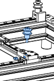
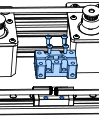
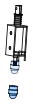
Install the capacitive stylus tip on the push-pull solenoid. Then install the two together onto the X carriage.
4949
TOUCH ENDtapz_10PhysiClaw.ai
Install the stylus tip
The solenoid has a nut on its bottom end. 1. Remove the nut. 2. If the stylus tip has an M5 female thread, install an M3 female-to-M5 male adapter on the solenoid. 3. Install the stylus tip.
Make the leads longer
Before you install the solenoid on the mount, make the positive and negative leads longer. Refer to Wiring — Extend the leads.
Bill of materials
Component
Spec
Qty
Solenoid
12 V, 2×M3, 15 mm pitch
1
Stylus tip
Conductive fabric tip, Ø7 mm
1
5050
TOUCH ENDtapz_11PhysiClaw.ai
Ten hole pairs for height adjustment
The mount has 10 pairs of holes, 1 mm apart. Pick one pair now. Later you can raise or lower the stylus in 1 mm steps.
Route the power leads
1. Feed the +/− leads of the solenoid into the rectangular hole in the side of the mount, as shown. 2. Run the leads up and out through the rectangular hole at the top.
Ground the solenoid
1. Clamp the bare copper of the ground wire between the solenoid housing and the mount. 2. Tighten one of the 2 mount screws to clamp it. 3. Run the ground wire out through the other rectangular hole below to join the power leads.
Use 6 mm long bolts
Longer bolts can push against the coil and cause damage.
Bill of materials
Component
Spec
Qty
Solenoid mount
SLS/MJF 3D Print
1
BHCS
M3×6
2
5151
TOUCH ENDtapz_20PhysiClaw.ai
Install the solenoid on the belt clamp
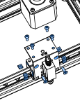
Install the solenoid assembly on the belt clamp with 6 screws. To change the stylus height later, move the assembly to a different hole pair.
Bill of materials
Component
Spec
Qty
BHCS
M3×8
4
FHCS
M3×10
2
Square nut
M3
6
5252
PhysiClaw.ai
SECTION 07
Phone bed
Two cross-beams mount under the frame and carry the printed phone bed. The phone lies in the bed with the screen up, level under the stylus. Its top-left corner sits against the corner of the bed.
5353
PHONE BEDphone_10PhysiClaw.ai
Build two cross-beams
Build two identical cross-beams for the bed.
Bill of materials
Component
Spec
Qty
Extrusion 1020
230 mm, M5 end holes
2
BHCS
M5×16
4
T-nut
Drop-In M5
4
5454
PHONE BEDphone_20PhysiClaw.ai
Bill of materials
Component
Spec
Qty
Phone bed
SLS/MJF 3D Print
1
FHCS
M3×8
4
T-nut
Drop-In M3
4
5555
PHONE BEDphone_30PhysiClaw.ai
Seat the bed on the beams
1. Lay the two cross-beams parallel, slotted faces up. 2. Lower the hanging T-nuts of the bed into the slots. 3. Tighten the screws.
5656
PHONE BEDphone_40PhysiClaw.ai
Install the phone bed
It is far easier with the frame upside down. 1. Turn the frame over, underside up. 2. Slide the T-nuts of each beam into the slots under the frame.
Put the phone in place
Put a phone on the bed, against the top-left corner. Slide the X carriage over the whole screen. Make sure that the stylus tip reaches every part of the screen.
Set the solenoid height
Set the solenoid height so that the stylus tip just makes stable contact with the screen. If the solenoid is too low, it cannot pull in fully. The magnetic force is then too weak to hold the tip down. The tip springs back, so long presses and swipes fail. If the solenoid is too high, the tip cannot reach the screen, or the contact patch is too small.
Keep the screen flat
The rear camera bump lifts one corner, so the phone does not lie flat. Put a piece of thin card or a few sheets of paper under the low edge. Add more until the screen is level. Make sure that the phone cannot rock or shift when the stylus taps. Any tilt or wobble causes missed taps.
5757
PhysiClaw.ai
SECTION 08
Control board
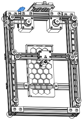
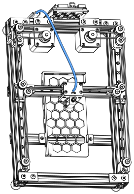
The control board mounts at the front of the frame. Spiral wrap binds the solenoid's lead wires to a Teflon tube. The tube stiffens the bundle so that it holds its shape, clear of the motors and belts. The tube anchors to the tube holder on the frame and to the X carriage.
5858
CONTROL BOARDboard_10PhysiClaw.ai
Install the T-nuts
Thread 2 M5 FHCS into the T-nuts. Do not fully tighten until the next step.
Bill of materials
Component
Spec
Qty
Control board holder
SLS/MJF 3D Print
1
FHCS
M5×12
2
T-nut
Drop-In M5
2
5959
CONTROL BOARDboard_20PhysiClaw.ai
Install the control board holder
Install it on the outer face of the top extrusion.
6060
CONTROL BOARDboard_30PhysiClaw.ai
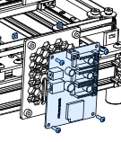
Install the control board
Use 4 screws with nuts. The figure does not show the 2 lower nuts.
Bill of materials
Component
Spec
Qty
Control board
MKS DLC32 V2.1
1
BHCS
M3×10
4
Square nut
M3
4
6161
CONTROL BOARDboard_31PhysiClaw.ai
Install the T-nuts
Thread 2 M5 FHCS into the T-nuts. Do not fully tighten until the next step.
Bill of materials
Component
Spec
Qty
Tube holder
SLS/MJF 3D Print
1
FHCS
M5×12
2
T-nut
Drop-In M5
2
6262
CONTROL BOARDboard_32PhysiClaw.ai
Install the tube holder
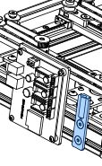
Install it on the top extrusion, beside the control board. Its 4 mm hole holds the fixed end of the Teflon tube.
6363
CONTROL BOARDboard_40PhysiClaw.ai
Rough length
Cut the tube to about 400 mm. It must reach from the tube holder to the X carriage at its farthest position.
Anchor the solenoid leads
Tie the solenoid leads to the tube holder with a cable tie. Otherwise the solenoid's travel shakes the lead wires at the control board terminals. Constant shaking works the contact loose, and then the solenoid no longer taps the screen.
PTFE vs FEP
Use either tube, PTFE (milky white) or FEP (clear).
Bind the wires with spiral wrap
Bind the solenoid's lead wires to the Teflon tube with spiral wrap along its full length. Do not put the wires inside the tube.
Bill of materials
Component
Spec
Qty
Teflon tube
Ø4/2, 400 mm
1
Spiral wrap
Ø4, ~400 mm
1
6464
PhysiClaw.ai
SECTION 09
Camera
The camera mounts on the right side of the frame and faces the phone screen.
6565
CAMERAcamera_10PhysiClaw.ai
1/4-20, not metric
The SHCS and hex nut for the gooseneck are 1/4-20, the imperial tripod thread (≈ 6.35 mm). Do not use an M6 instead.
Imperial tools
The 1/4-20 SHCS takes a 3/16" hex key. The 1/4-20 hex nut takes a 7/16" (or metric 11 mm) open-end wrench. Needle-nose pliers also do the job. There is no need to buy tools for this.
Bill of materials
Component
Spec
Qty
Corner bracket
2×Ø6.5 mm
1
BHCS
M5×10
1
T-nut
Drop-In M5
1
SHCS
1/4-20×16 (imperial)
1
Hex nut
1/4-20 (imperial)
1
6666
CAMERAcamera_20PhysiClaw.ai
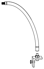
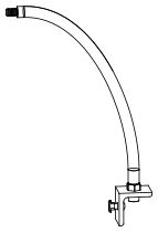
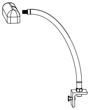
Thread on the gooseneck
Thread the gooseneck's female end onto the stud until it is tight against the hex nut.
Bill of materials
Component
Spec
Qty
Gooseneck
Ø10×300, 1/4-20 M/F
1
6767
CAMERAcamera_30PhysiClaw.ai
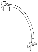
Thread on the camera
Thread the camera's 1/4-20 female thread onto the gooseneck's male stud until it stops against the collar.
Bill of materials
Component
Spec
Qty
Camera
4K HD, autofocus
1
6868
CAMERAcamera_40PhysiClaw.ai
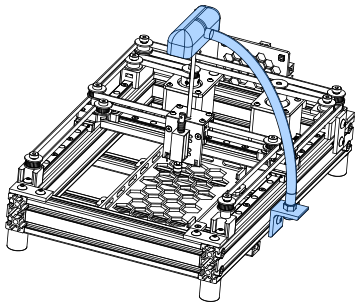
Use the lower slot
Install the corner bracket in the lower slot of the right extrusion's outer face.
Orient the camera
Bend the gooseneck so that the camera points squarely at the phone screen. Align the sensor's long edge with the phone's long edge.
Check the camera
Make sure that the camera does not drift or wobble.
Route the USB cable
Tie the camera's USB cable along the gooseneck with cable ties, clear of the belt.
6969
PhysiClaw.ai
SECTION 10
Wiring
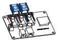
Connect the stepper driver outputs of the control board to the motors. Connect the solenoid to the Spindle output. Ground the solenoid.
7070
WIRINGwire_10PhysiClaw.ai
Power off first
While the board is powered, never plug in or remove a driver.
Note the orientation
Do not install a TMC2209 reversed. It can burn out when the power comes on. Before you press a driver into its header, make sure that its pin labels match the silkscreen.
Rule of thumb
Match colored to colored, black to black.
Heatsink
TMC2209 driver modules usually include a heatsink. Stick it on top of the driver chip.
Bill of materials
Component
Spec
Qty
Motor driver
TMC2209
2
7171
WIRINGwire_10PhysiClaw.ai
Motor B (X)
Motor A (Y1)
Solenoid (spindle)
Power (DC in)
USB Serial Port
Motor A
Motor B
Connections
The board uses standard GRBL axis outputs, remapped as follows: the X-axis stepper driver drives Motor B, the Y1-axis stepper driver drives Motor A, and the Spindle output drives the solenoid.
No polarity
Connect either solenoid lead to either Spindle terminal.
Motor cable connectors
The motor side is a 6-pin PH2.0 (2.0 mm pitch); 2 pins stay empty. The board side is a 4-pin XH2.54 (2.54 mm pitch). Each connector is keyed and fits in one orientation only. Align the key on the plug with the notch on the socket. Do not force the plug in.
Bill of materials
Component
Spec
Qty
Power adapter
12 V 2 A
1
Motor cable
XH2.54
2
Data cable
USB serial
1
7272
WIRINGwire_splicePhysiClaw.ai
Extend the leads
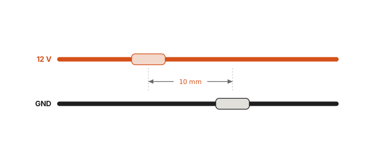
The solenoid's stock leads do not reach the control board. Splice lead wire onto both the 12 V and GND leads.
Keep the stock leads under 50 mm
Before you splice, cut the solenoid's stock leads back to 50 mm or less. The joints then sit clear of where the cable bends most. A joint that flexes with every gesture fatigues and snaps.
Stagger the joints
Stagger the two joints by about 10 mm. Do not put them side by side.
Connect the wires
Solder each joint. Cover each joint with heat shrink tubing. If you cannot solder, twist the wires together. Wrap each joint tightly with electrical tape.
Bill of materials
Component
Spec
Qty
Lead wire
0.3 mm²
1
7373
WIRINGtapz_10PhysiClaw.ai
Ground the stylus
The stylus rides on the solenoid's iron core. The metal return spring ties the core to the housing. Do not use the control board's GND. Ground the housing. The core and the stylus tip are then grounded too.
Why the ground matters
A capacitive screen senses a touch through capacitive coupling to ground. A finger works because the body is a large conductor tied to earth. An ungrounded stylus couples to earth too weakly. A tap then shifts the screen's charge distribution only slightly, and the phone registers the touch unreliably. A verified ground restores that coupling and steadies the touch.
How to ground the housing
Never put the ground wire into a wall outlet. Connect the housing to earth ground. The simplest option is a desktop PC chassis grounded through a three-prong outlet. Clip the wire to bare metal on the chassis. The chassis reaches earth through the mains and gives a stable reference.
Three wires
The solenoid has three wires: positive (+), negative (−), and ground. 1. Bind the ground wire into the bundle with the + and − leads. 2. Run the bundle up to the control board holder. 3. Connect + and − to the control board's Spindle terminals.
Warning
Never put the ground wire into a wall outlet. Mains voltage (220 V/120 V) is lethal. If the wire touches the live terminal instead of earth, the shock is fatal. The same contact destroys the phone and the equipment instantly. Connect only to a verified ground point.
7474
PhysiClaw.ai
SECTION 11
Bill of materials
This is the complete parts list for the whole machine. Use it to gather every part before you start assembly.
7575
Bill of materials11 — BOMPhysiClaw.ai
Class
Component
Spec
Qty
Application
Frame
European Standard Anodized Black Aluminum Profile Extrusion 2040 T Slot
Length 345 mm, two M6 counterbores at each end on the 40 mm-wide face, 10 mm from the end face, for M6 SHCS
2
Frame side rails
Length 190 mm, both ends tapped M6
2
Frame end rails
European Standard Aluminum Profile Extrusion 1020
Length 185 mm
1
Gantry X beam
Length 230 mm, M5 through-hole 10 mm from each end
2
Phone bed cross-beam
Custom parts
3D printed parts
Selective Laser Sintering (SLS) or Multi Jet Fusion (MJF), PA12 nylon (or equivalent), black
11
Idler mount (2 front, 2 rear), XY joint (left), XY joint (right), Belt clamp, Solenoid mount, Phone bed, Control board holder, Tube holder
Linear guide
MGN9H rail
Rail length 240 mm
2
Y-axis rails
Rail length 150 mm
1
X-axis rail
MGN9H carriage
H-type long carriage, 4×M3, 15 × 16 mm mounting hole pitch
3
One per rail
Motion components
Pulley
GT2 20T, 5 mm bore, 6 mm width
2
Motor drive pulleys
Idler
GT2 20T smooth, 5 mm bore, 6 mm width
10
CoreXY belt redirection
GT2 20T toothed, 5 mm bore, 6 mm width
2
CoreXY belt redirection
Timing belt
GT2, 6 mm width, 5 m/roll
1
CoreXY belt
7676
Bill of materials (cont.)11 — BOMPhysiClaw.ai
Class
Component
Spec
Qty
Application
Electronics
Control board
MKS DLC32 V2.1 (incl. USB cable)
1
Main controller
Stepper driver
TMC2209
2
Motor drivers
Power supply
12 V 2 A adapter, 5.5×2.1 mm barrel plug
1
System power
Camera
4K HD USB webcam, autofocus
1
Overhead screen view
Wiring / Cables
Motor cable
XH2.54, 4-pin, 200 mm
2
Stepper motor → control board
Lead wire
0.3 mm² stranded flexible wire, pure copper core, 2 m
1
Solenoid ground & leads
Actuators
Stepper motor
NEMA 17, 38 or 40 mm height
2
Drive motors
Solenoid
12 V, 0.8 A, 10 mm stroke, 0.2–6 N push-pull, 2×M3 mounts, 15 mm pitch
1
Drives the stylus tip to tap
Hardware
Flat bracket
40 × 18 × 4 mm (L×W×T), 20 mm hole pitch, M5 holes
6
Frame & idler joints
Motor bracket
60 × 42 × 3 mm (L×W×T)
2
Motor brackets
Corner bracket
2-hole right-angle bracket, 26 mm long, 30 mm leg, 2×Ø6.5 holes
1
Camera bracket
Bumper
Cylindrical, 20 mm diameter, 22 mm height, incl. machine screw
4
Frame feet
Stylus tip
M3 female thread, Ø7 mm fabric tip, Ø8.5 mm OD, 12.5 mm height
1
Tip that taps the screen
Teflon tube
2 mm ID, 4 mm OD, 1 m, PTFE or FEP
1
Stiffens the lead bundle
Spiral wrap
Ø4 mm, ~0.5 m
1
Binds the wire to the tube
Gooseneck
360° adjustable, 1/4-20 M/F, 300 mm long, 10 mm OD
1
Camera arm
7777
Bill of materials (cont.)11 — BOMPhysiClaw.ai
Class
Component
Spec
Qty
Application
Fasteners
BHCS
M3×6 (thread dia × thread length)
10
Motors & solenoid mount
M3×8
39
Rails, belt clamps & solenoid mount
M3×10
4
Control board mount
M5×10
15
Frame, idlers, camera bracket
M5×12
2
Flat brackets at the idler mounts
M5×16
10
Frame, phone bed & Motor A bracket
M5×20
2
Motor B bracket
FHCS
M3×8, length = overall (incl. head), not thread length
4
Phone bed
M3×10
10
XY joints & solenoid mount
M5×12
6
Gantry, control board holder & tube holder
SHCS
M6×20
8
Frame joints
1/4-20×16, imperial (≈ 6.35 mm), not interchangeable with M6
1
Camera arm
Shoulder screw
Ø5×10×M4 (shank dia × shank length × thread)
4
Idler
Ø5×20×M4
6
Idler
7878
Bill of materials (cont.)11 — BOMPhysiClaw.ai
Class
Component
Spec
Qty
Application
Fasteners
T-nut
Drop-In M3
35
Gantry & phone bed
Drop-In M5
23
Frame, idlers, phone bed, control board holder, tube holder, camera bracket
Slide-In M5
10
Frame & gantry
Square nut
M3, 5.5 mm square, 2.4 mm thick
10
Solenoid mount & control board holder
M4, 7 mm square, 3.2 mm thick
10
Idler
M5, 8 mm square, 4 mm thick
2
Idler
Hex nut
1/4-20, imperial (≈ 6.35 mm), not interchangeable with M6
1
Camera arm
Shim
5 mm ID, 8 mm OD, 0.5 mm thick
12
Idler
Spacer
5 mm ID, 10 mm OD, 9 mm height
4
Idler
6 mm ID, 12 mm OD, 8 mm height
2
Motor A bracket standoff
6 mm ID, 12 mm OD, 12 mm height
2
Motor B bracket standoff
Tools
Hex key
2 / 3 / 5 mm
3
M3, M5, M6 screws
Other
Grease
Lithium grease, NLGI 2
1
Rail lubrication
Threadlocker
Loctite 243 or equivalent — medium strength, blue
1
Lock pulley set screws
Heat shrink tubing
Ø3 mm
2
Insulate the solder joints
7979
END OF MANUAL
Next, tell PhysiClaw what you'd like it to do.
“PhysiClaw can do anything you can do on your phone. It looks at the screen and touches it, just like you.”